


The Ideal Lift


 |
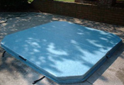
Ideal Spa Covers was the first to introduce this style of lift, and
the first to take it to the next level. Taking five years to develop, this spa cover lift
incorporates the best in engineering and design. |
|
|

Installation / Operating requirements and limitations |
||||||
| rear clearance | side clearance | spa/cabinet shape limitations | mounting location | spa corner shape limitations | type of lift assistance | min. [max.]cover width |
| 5" | 0 if top mounted. 4" if side mounted | deck or spa side | gas shock | |||
See the complete Cover Lift Configurater to compare all cover lifters side by side. |
||||||
|
|
|
|
|
|
Installation Instructions for the Ideal Cover Lift
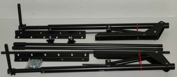
What's actually inside the box.
| The following parts are included in your Ideal Cover
Lift package: Two (2) Pre-assemble Pivot Assemblies |
The following are needed to install your Ideal Cover Lift; Power drill
with 1/4" drill bit |
WEAR PROTECTIVE EYE WEARWARNING: ALL HARDWARE MUST BE PROPERLY TIGHTENED BEFORE OPERATION OF LIFT. FAILURE TO DO SO MAY RESULT IN INJURY OR DAMAGE TO LIFT OR SPA. |
CAUTIONS |
Extreme Caution:
- Be sure to use extreme caution during the Hydraulic Lift Arm phase of the assembly. A potential for sudden impact is possible.
- Do not cut the RED retaining straps until instructed to do SO.
- BEFORE ASSEMBLY: Make sure there are no overhead objects that could interfere with the cover's designed operation (lights, wires, branches, etc.).
-NEVER!!! disassemble the pre-assemble Pivot Assembly.
- Be sure to read all installation steps before beginning.
- Many steps only show the installation of your cover lifter on one side of your hot tub.
- To complete your installation, repeat the same steps on the opposite side of your hot tub.
DETERMINING WHICH TYPE OF INSTALLATION IS RIGHT FOR YOUR SPA / HOT TUB
PLEASE consider the following before installing your Cover Lift:
The Channel Bracket (pre-assembled Pivot Assembly) should be mounted 2-5" from the back edge of your hot tub.
The Pivot Assembly should not interfere with your hot tub cover.
Determine whether or not the Side Mount Brackets are necessary for installing the Cover Lift to your hot tub. (See A & B below)
A. Use the Side Mount Brackets to assemble your Cover Lift when:
- the top rail around your hot tub is not wide enough to accommodate the Channel Bracket of the Pivot Assembly or
- the Cover Lift is the same size or wider than the wood rim of your hot tub's cabinet.
B. Do not use the Side Mount Brackets to assemble your Cover Lift when:
- the Channel Bracket of the Pivot assembly can be mounted directly to the deck of an in-ground hot tub or
- the Channel Brackets can be mounted directly to the top of your hot tub's cabinet without interfering with the Cover Lift.
Channel Bracket is mounted directly on top of the wood rim cabinet. The cover mover freely between the cover lift and spa.
Side Mount Bracket is mounted to the side of the hot tub's cabinet in order to leave room for a cabinet size cover.
Side Mount Bracket is mounted to the side of the hot tub's top rail on the first flat surface 2" - 5" from the corner of the tub.
Channel Bracket is offset of the top of the Side Mount Bracket; bringing the Pivot Assembly 2" - 5" from the back edge of the hot tub cover.
ASSEMBLY A. Mounting Brackets
- Install Mounting Brackets so that when the cover is lifted it is on the side opposite the control panel of the hot tub.
- Measure 1 1/2" from end of cabinet edge (from kitty corner flush to cut line).(figure1)
- Mark holes, on center, with marker on both sides of hot tub. (figure 1)
- Use one bracket or level to level the bracket while marking and drilling holes.
- Drill holes on bracket marks to a depth of 3/4" using 1/4" drill bit.
- Using a 1/2' socket wrench, install Mounting Brackets with screws provided.
B. Hydraulic Lift Arm
Extreme Caution: Be sure to use extreme caution during this phase of assembly. A potential for sudden impact is possible. Do not cut the RED retaining straps until instructed to do so.
- Using a 9/16" socket wrench, loosen the nut (shipping bolt) marked "Under pressure". (figure 2)
- Remove the Shipping Bolt and replace it with the Lock Knob making sure that the conical spring washers are facing concaved sides towards each other (see figure 3)
- Tighten the Lock Knob till it offers firm resistance.
- Making sure extension bar is pointed away from your face and other body parts.
- Make sure Lock Knob is tightened
- Cut RED retaining strap and discard strap.
- The Gas Shock of the Pivot Assembly is under pressure. Use extreme caution on steps 8 and 9.
- Placing Channel Bracket on ground, place hand over Extension Bar and exert force downward while slowing loosening the Lock Knob.
- Gently release pressure exerted from hand on Extension Bar assembly and allow the gas shock to expand to full extension.
Figure 2
Figure 3C. Pivot Assembly Installation
Side Mount Bracket Installation
- With Pivot Assembly fully expanded, place five (5) 1/2" bolts with washers through holes in Assembly and Side Mount Bracket carefully lining up same (figure 4).
- Secure with NYLOCK NUTS, but DO NOT TIGHTEN.
- Once bolts are in place, slide assemble as far away from the side of cabinet as it will go.
- Tighten bolts starting with the center bolt and alternating till all bolts are tightened down.
No Side Mount Bracket Required Installation
- With Pivot Assembly fully expanded, place five (5) 1/2" bolts with washers through holes in Assembly and line up carefully with holes in top or side of hot tub cabinet (figure 5).
- Secure with nuts, but DO NOT T1GHTEN.
- Once bolts are in place, tighten bolts starting with the center bolt and alternating till all bolts are tightened down.
Figure 4
Figure 5Cover Assembly
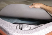
- Gently place the folded Cover Lift cover on top of hot tub with the cover's seam (fold) facing the control panel so that the flap on the cover is flush with the edge of the cabinet.
- Loosen the Lock Knob and pull the Extension Arm to a horizontal position.
- Using a Phillps head screw driver, remove the screw and nut from the adjustable arm.
- Now, slide the Extension Arm until it sits between the fold's flaps along the cover's fold seam. (figure6)
- Line up the hole in the adjustable arm and replace the screw and nut.
- Now, flip the one half of the folded cover over until it covers the remainder of the hot tub.
- Take one of the Handle Bars and insert it into the top of the Molded Saddle, located on the end of the Extension Bar.
- Using a 2 1/2" bolt and Nylock Nut, fasten the Handle Bar to the Extension Bar. Be sure to tighten until at least one thread of the bolt is through the Nylock Nut.
- Insert the Torsion Bar into squared end of the mounted Handle Bar, then insert the opposite end of the Torsion Bar into the remaining Handle Bar. Be sure to put equal amounts of the Torsion Bar into each Handle Bar.
- Using a 2 1/2" bolt and Nylock Nut, secure the other Handle Bar to the Molded Saddle of the remaining Extension Arm .
OPERATION Lifting
- Before lifting the cover, make sure there is nothing on the cover.
- Look to see that there is no overhead obstruction that could interfere with the covers trajectory (lights, wires, branches etc.)
- To lift the cover, simply grab a hold of either Handle Bar, and lift in an upward motion.
- The hydraulic arm of the Cover Lift will provide will provide the necessary power to assist in lifting the cover.
- Bring the cover to its full upright position, the cover will hang slightly towards the hot tub, tighten the lock knob for extra secure hold of cover. Loosen knob to lower and tighten again when closed.
- The Cover Lift cover provides excellent heat retention when in place, and acts sound baffle and privacy screen when in the lift position.
|
|
|
|
|
|